Heat Pump Defrost Board Schematic

Diagram Goodman Heat Pump Defrost Control Board Wiring Diagram Full Version Hd Quality Wiring Diagram Diagramy Pat Pizza Fr

Heat Pump Manual Defrost

Heat Pump Defrost Board Wiring Question Doityourself Com Community Forums
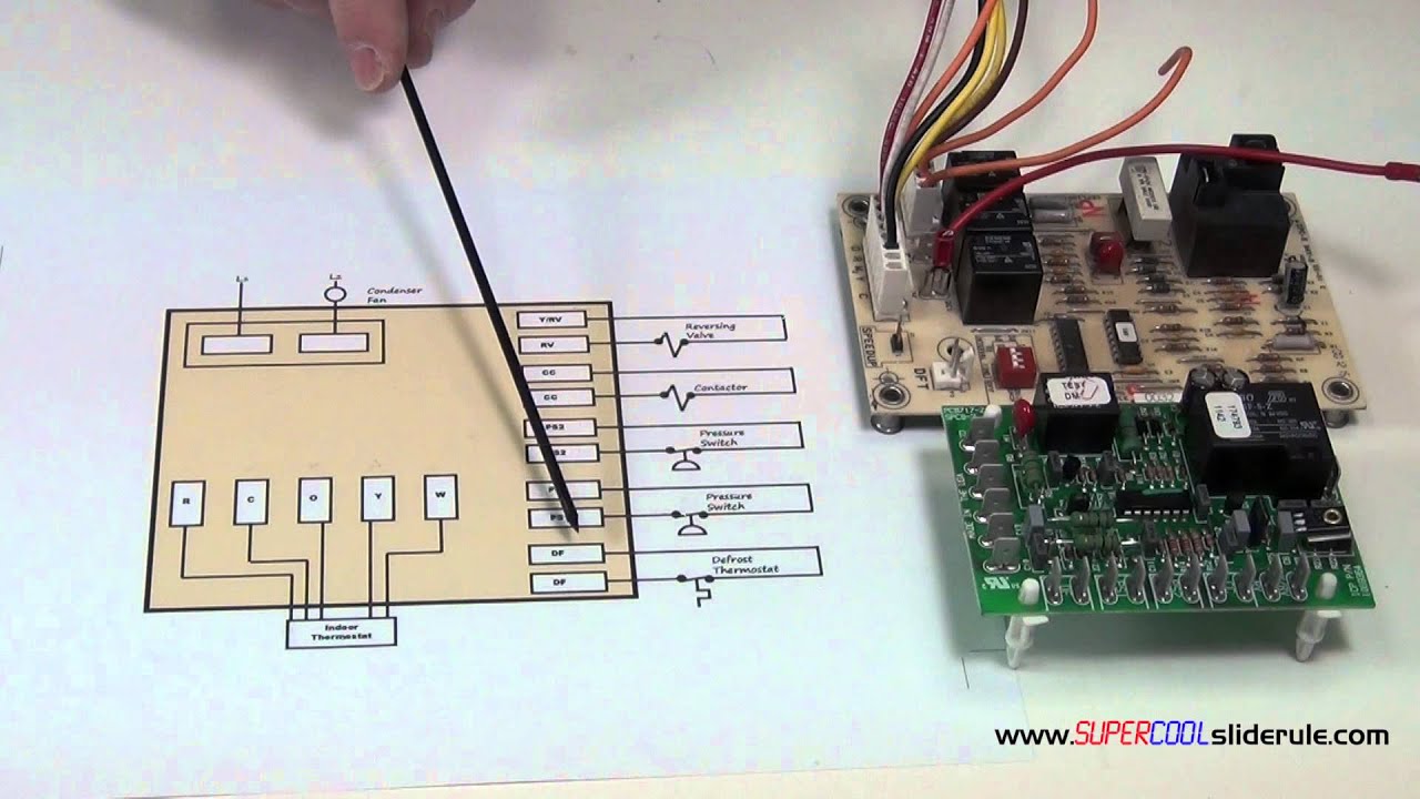
Heat Pump Diagram 3 Call For Defrost Sequence Youtube

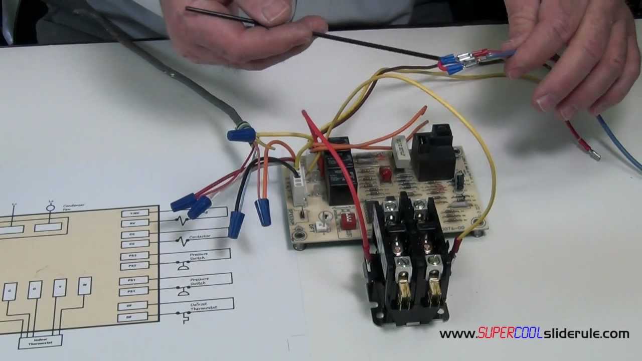
Heat Pump Defrost Control Boards Step By Step
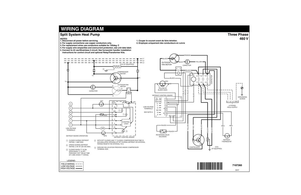
Wiring Diagram Split System Heat Pump Three Phase 460 V Manualzz
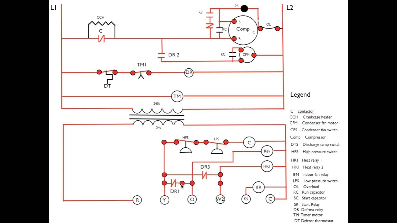
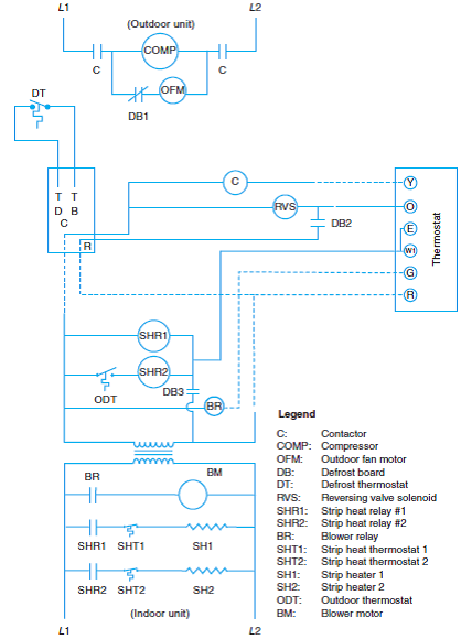
W2 out output to energize 2nd stage heat when in defrost w1 66 used to energize 1st stage heat when in defrost.
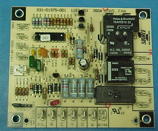
Heat pump defrost board schematic.
American Standard Pump Wiring Diagram Diagram Base Website Wiring Diagram Venndiagram Manifestazionipiemonte It

Goettl Heat Pump Wiring And Troubleshooting I Need A Very Experienced Tech Goettl Hp425j With 2 Stage Heat Honeywell

Defrost Cycle No Auxiliary Heat Hvac Diy Chatroom Home Improvement Forum

Cnt05001 American Standard Trane Defrost Control Board

How This Defrost Control Board Works Heat Pump Wiring For Defrost Cycle Youtube
Heat Pump New Heat Pump Defrost Board
How To Bypass A Defrost Heat Pump Board To Allow Cooling Youtube
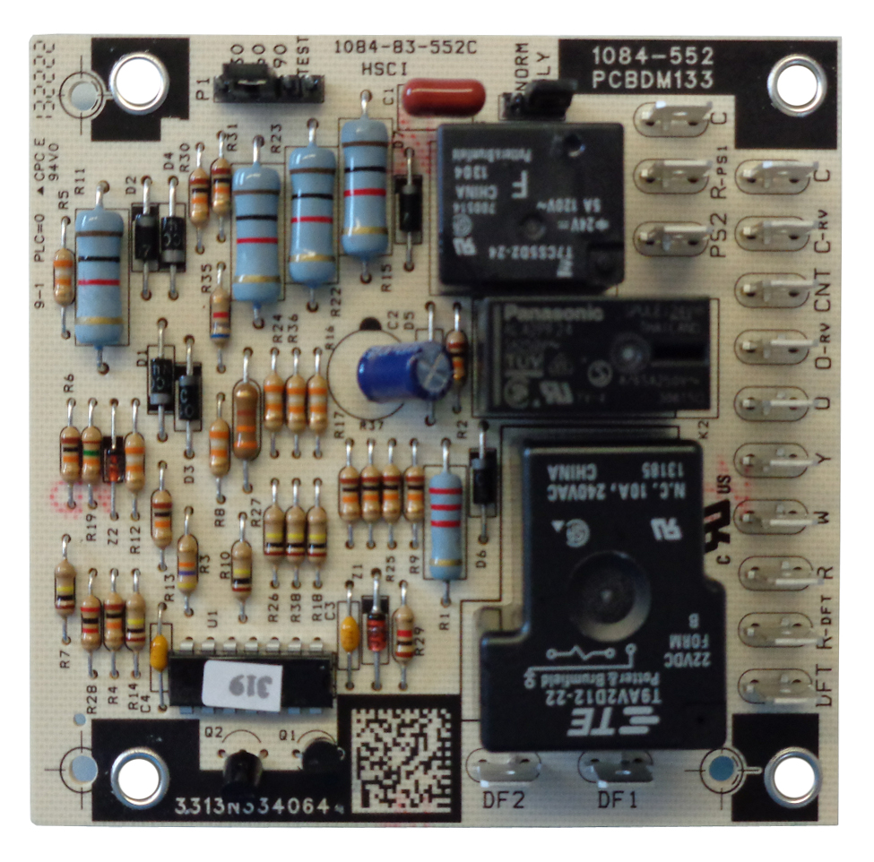
Circuit Board Pcbdm133s Pcbdm160s Defrost Control Board Goodman Repair Parts

47 21776 86 Rheem Ruud Heat Pump Defrost Control Board

Lg 6981 Hvac Defrost Wiring Connection Diagram Download Diagram
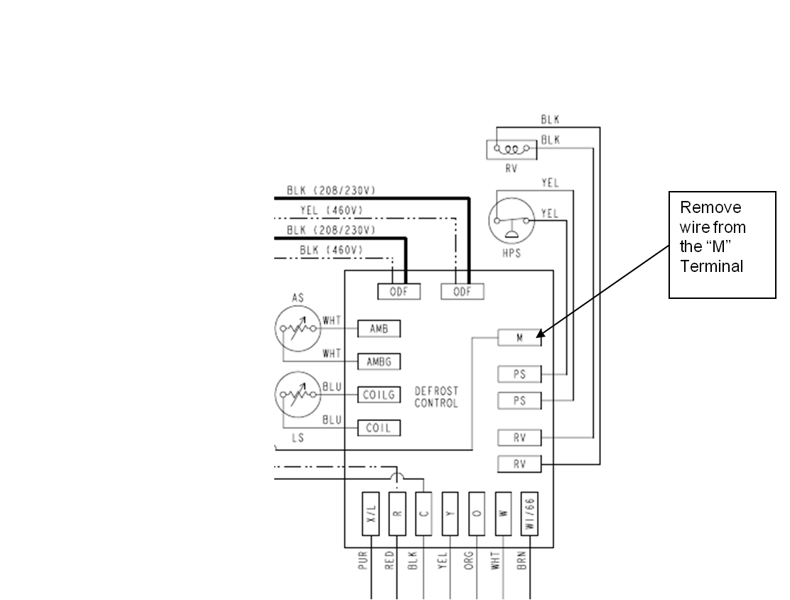
Diagram Diagram Timer Carrier Wiring Defrost 38cq660 Full Version Hd Quality Defrost 38cq660 Diagrammatix Nuitdeboutaix Fr

1087952 Icp Heil Tempstar Heat Pump Defrost Control Board Arnold S Service Company Inc
Solved Use Figure 6 40 To Answer Questions The Defr Chegg Com

Defrost Board Problem Doityourself Com Community Forums

Ol 6213 Wiring Diagram Further Goodman Heat Pump Defrost Board Wiring Diagram Download Diagram

Heat Pump Defrost Board Troubleshooting Youtube
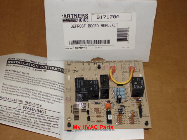
Nordyne 917178 Defrost Control Board

Carrier Heat Pump Manual Defrost
Https Encrypted Tbn0 Gstatic Com Images Q Tbn 3aand9gct6ynn55tqsqahm2rbap5n3wymltfss6hjmvvb84uclr6mdyche Usqp Cau
Hvac Defrost Timer Wiring I 39 Ve Purchased A Icm 315 Defrost Timer Control Board For A Defrost Termination Archives Hvac School Circuit Diagram Help Heat Pump Diagram 3 Call For Defrost

Diagram Defrost Board Wiring Diagram Full Version Hd Quality Wiring Diagram Diagrammatix Nuitdeboutaix Fr

Hvac Controls Pcbm130 Defrost Controller Youtube

Oem Rheem Ruud Weather King Corsaire Defrost Control Board Sensor 47 21517 14 For Sale Online

Freezer Defrost Timer Wiring Diagram 2 Circuit Diagram Electrical Wiring Diagram Electrical Circuit Diagram
Source : pinterest.com
